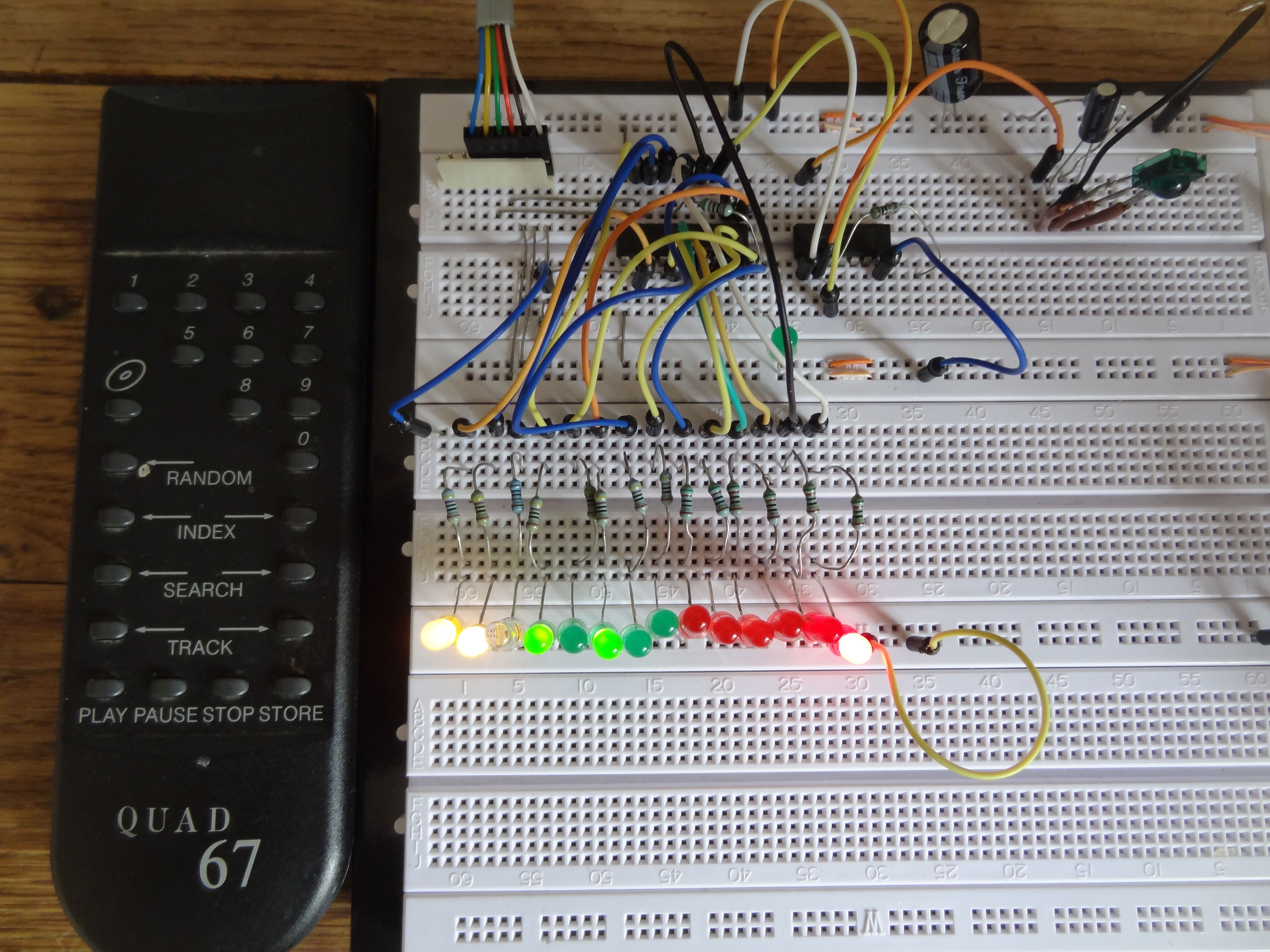
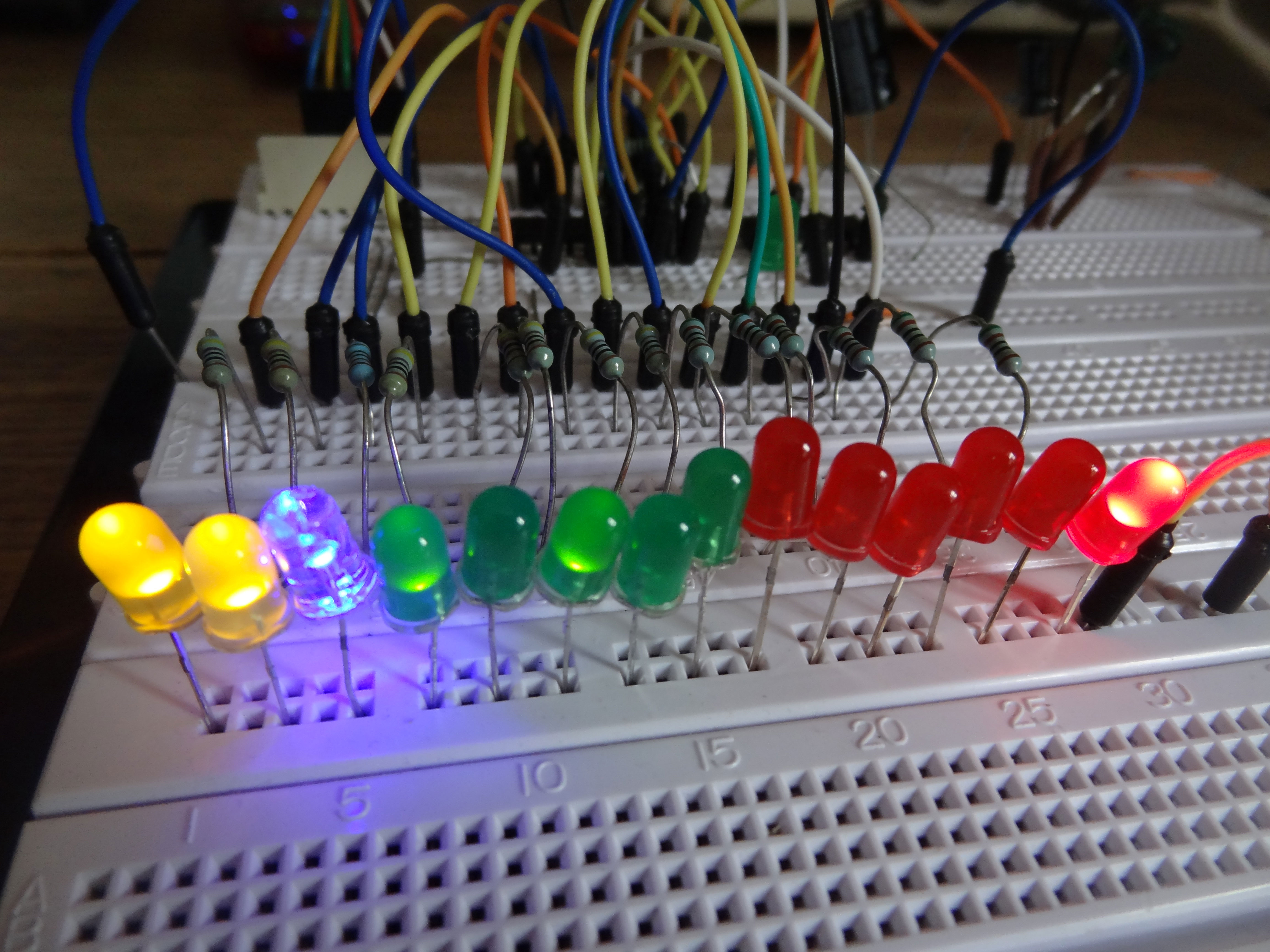
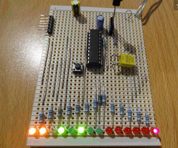
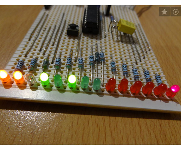
Electronics giant Philips invented the RC5 protocol for controlling electronic equipment such as CD players, VCR's and audio amplifiers way back in the 1980's. The RC5 standard has been adopted and used with great success ever since, which means it is probably the most common IR remote control format in your home today. We have recently been playing around with a PIC microcontroller based RC5 decoder programmed in C, with the purpose of testing any RC5 based remote handset you may have. The image above shows the RC5 code for a button press of '1' on the CD player remote control decoded into binary and displayed on the 14 LEDS - the address data for a CD player is '20' hence the 10100 binary pattern on the green LEDS. The RC5 command for '1' is unsurprisingly 000001 in binary as shown on the red LEDS. The two start bit LEDS (yellow) are showing 11 binary and the toggle bit is off. In the pic below the '1' button has been pressed again showing the toggle bit now being set (blue LED).
The RC5 protocol is based upon a 14 bit serial code (binary 0/1) - when a key is pressed on the remote, the following bits are emitted:-
bit 1 (start bit) S1
bit 2 (second start bit) S2
bit 3 (Toggle bit) T
bits 4 - 8 (5 device address bits) A4 A3 A2 A1 A0
bits 9 - 14 (6 command bits) C5 C4 C3 C2 C1 C0
Below is a diagram showing the 14 bit pattern and the pulse and space timings for a typical RC5 transmission. More information on RC5 including device address codes and commands can be found at the link below.
RC5 protocol
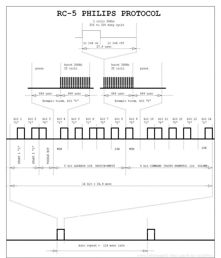
The data is encoded using Manchester or bi-phase encoding of the binary data, in order to maximise noise immunity. A logic '1' is represented by a low half bit followed by a high half bit, whilst a logic '0' is represented by the opposite pattern i.e a high half bit followed by a low half bit. The transition from high to low or low to high always occurs at the mid-bit point. The bit length is approximately 1778us, so the mid bit point is at 889us - in other words, each half bit is 889us long. Manchester encoded data can be decoded in one of two ways. The first method is to detect the direction of change at the mid-bit point (low to high or high to low). A high to low transition at the mid-bit point indicates a logic '0' whilst a low to high transition indicates a logic '1'. The second method involves simply reading the logic level present in the second half of the bit period, which is the method I used for this project.
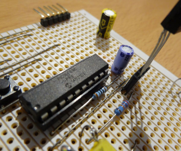
Here are a few pics of the prototype built on Veroboard. The IR sensor is a TSOP2236 three pin device. An in-circuit programming connector has been included to allow easy software revisions if required in the future.
 Prototype veroboard construction of the RC5 decoder
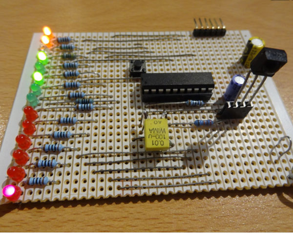
The RC5 decoding algorithm employed is written in C and is targeted at a PIC 16f690 microcontroller. A 36kHz IR receiver IC is used ( TSOP2236 but I also had good results from an old IS1U60L I had lying around) which removes the 36kHz carrier frequency from the transmitted RC5 code, leaving a binary bit stream which can be fed to the microcontroller. As the IR receivers have an active low output, inversion of the received data at PORTAbits.RA4 is easily achieved in software.
The RC5 protocol decoding takes place within the interrupt service routine (isr). Two interrupts are employed, an external interrupt on RA2 (negative edge triggered) and Timer 1 overflow interrupt. Once decoded the RC5 data is received on RB4.
The output of the IR sensor is logic 1 when no RC5 data is being received - upon the first RC5 transmission the output of the IR sensor goes low. An external interrupt on RA2 detects this initial high to low transition so we set S1 bit high, and then disable the external interrupt until the next 14 bit RC5 transmission starts. The TMR1 interrupt is now enabled and pre-loaded with 0xf92e to give a regular interrupt at 1780us, enabling us to sample the data level in the second half of each Manchester encoded bit, giving us the binary pattern of the original transmission. Timer 1 interrupt continues for the remaining 13 bits left to be decoded from the RC5 packet. Once the 14th RC5 bit has been decoded, the interrupts stop and the decoded RC5 data is displayed on the 14 LED's in the main loop.
In the main loop we have set up a one dimensional array of 14 elements to store the RC5 bits sequentially, incremented by index variable j. The RC5 bit pattern is then output on PORT's A, B and C to 14 LED's, so that the correct operation of the remote can be observed. For the prototype I made the S1 S2 bits yellow, T bit (toggle bit) blue, the device address bits green, and the command bits red. A further green LED is connected to PORTCbits.RC0 to indicate the receiving of RC5 data.
Here is the software listing which was compiled using XC8 - INT_TMR1_RC5.C
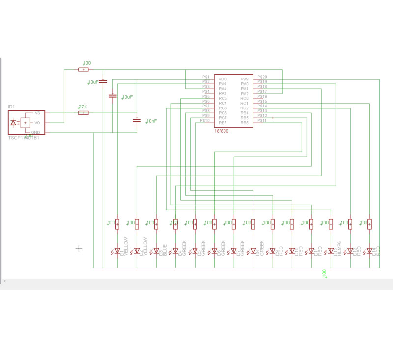
The schematic diagram is illustrated below. I hope you found this article interesting.