


I got to thinking that an interest in hi-fi can be a bit geek ( in a good way ) so I thought one of my latest geek projects might be of interest to some of you. You could build the project 'as is' without learning embedded C programming or you could use the project as a spring board to extra geekiness and weekend fun - I'll leave that to you :-)
Learning embedded C can be hugely rewarding and creative. The tool chain needed to get you started is either free (MPXLAB IDE and XC8 C compiler are both free downloads from the Microchip website and the pickit 3 needed to download compiled C code to your target microcontroller (16f690 in this case) is less than 50GBP.
You might be wondering why this project might be interesting to hi-fi enthusiasts. Well I have a few suggestions ... the finished project will allow you to keep tabs on the temperature of your listening room via an LM35 temperature sensor, which is important not just for your own comfort, but electro-mechanical devices such as turntables, phono cartridges and loudspeakers or headphones perform best at temperatures that are comfortable to humans like you and me - 18 Celcius to 23 Celcius for example.
The other feature, the 24 hour clock is simply a clock as implemented at the moment, which is always useful in a gadget, but with additional software development could be used to time the hours of phono cartridge use, or if you have a valve amplifier the hours of valve usage. Either way it's a great feature as it is and leaves further firmware development up to your imagination.
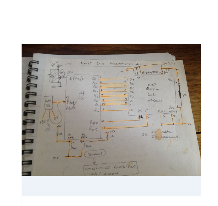
Here is a roughly drawn but accurate schematic circuit diagram and also the full C source code plus full build details - if you have any questions or queries please ask! Have fun...
Here is the finished prototype with a few changes in the firmware - degC now replaced with a more elegant representation, plus some fine adjustments to timer 1 overflow to fine tune the clock accuracy :-)
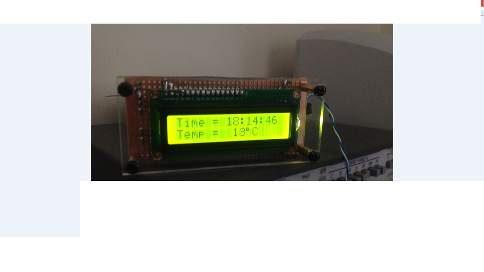
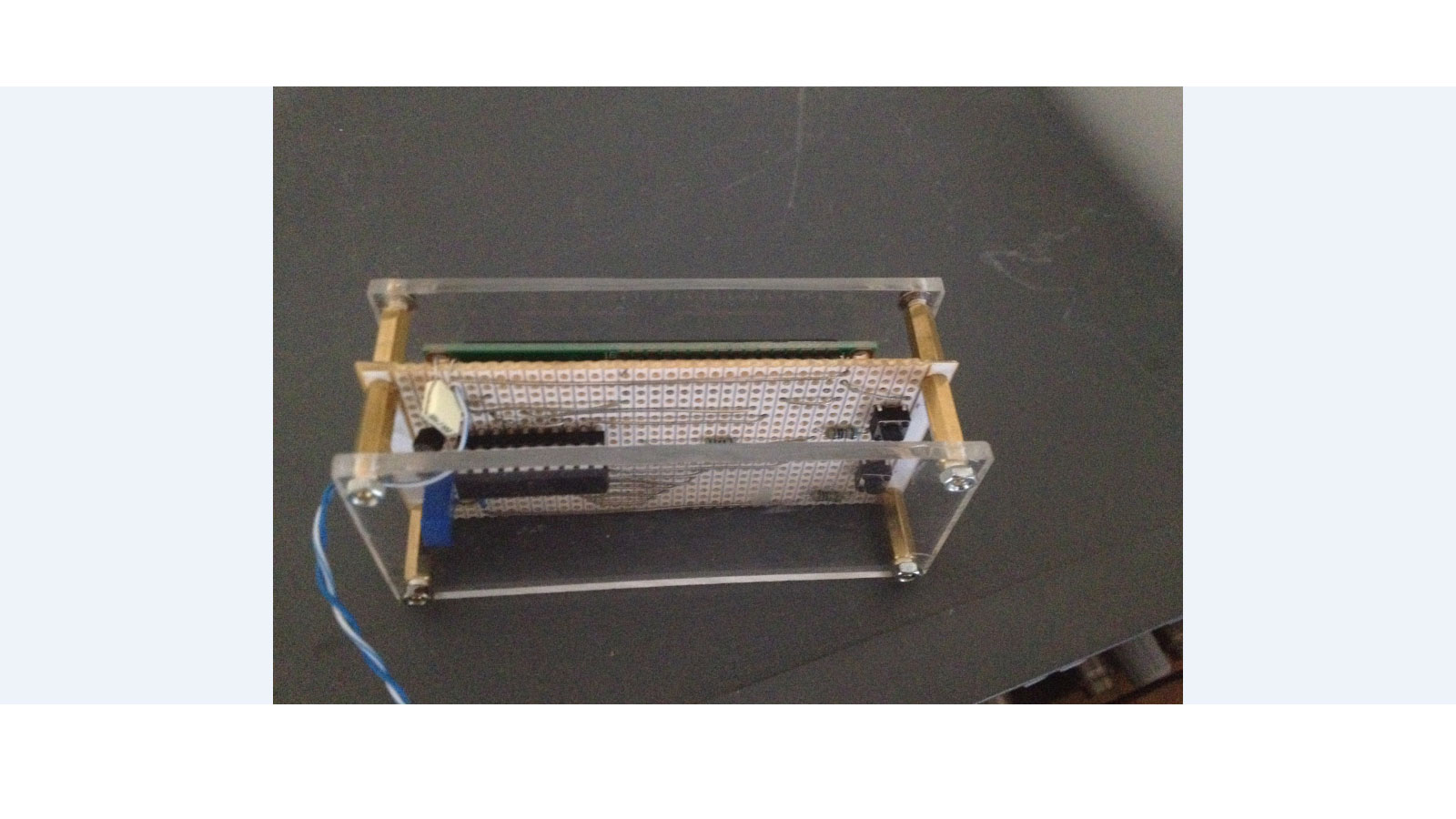
Here's a top view showing the sandwich construction of the thermo_timer - the front is a layer of 4mm clear acrylic, then brass pillars stand this off from the strip board circuit board. Another set of brass pillars then stand off the second layer of 4mm clear acrylic.
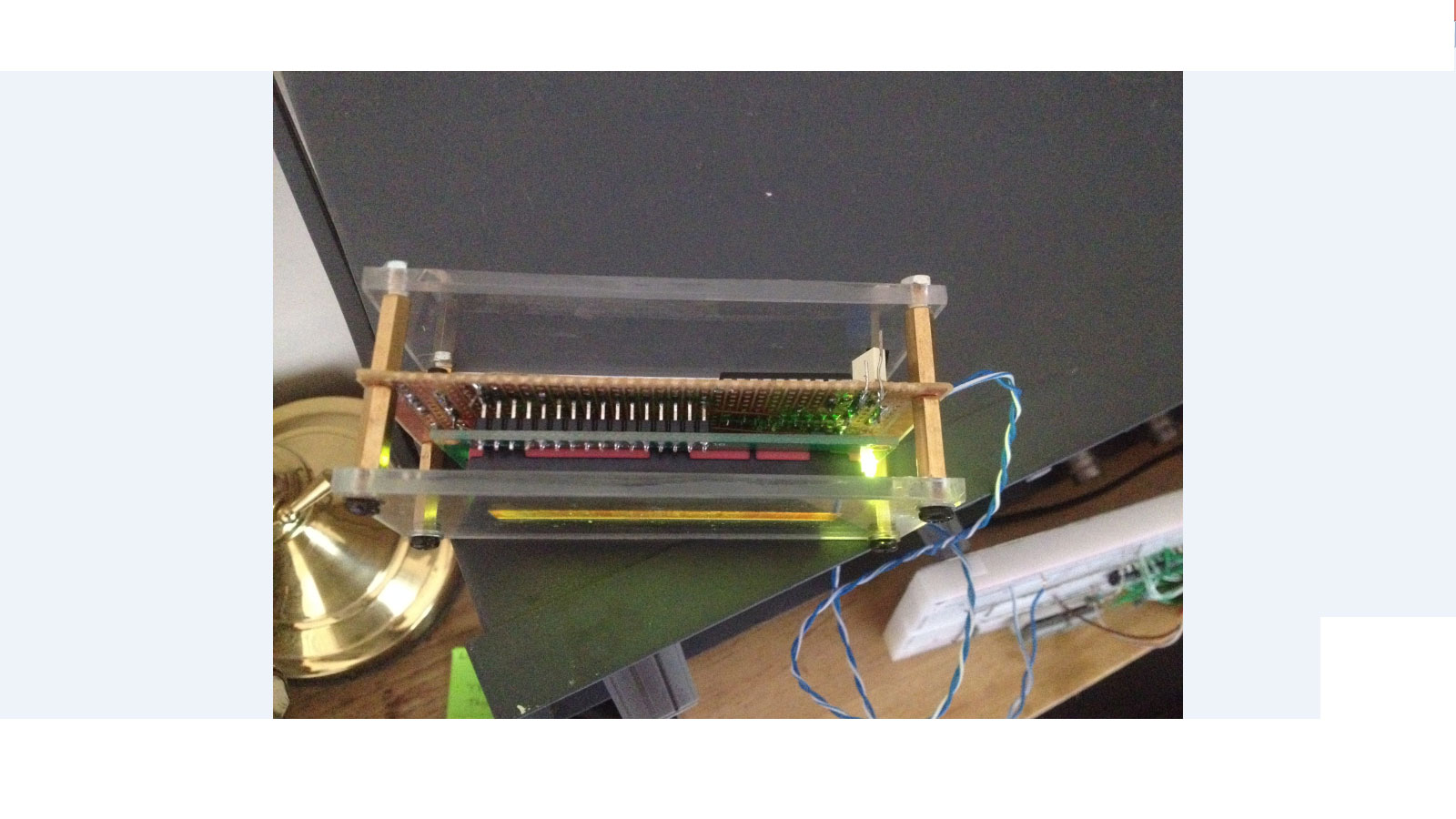
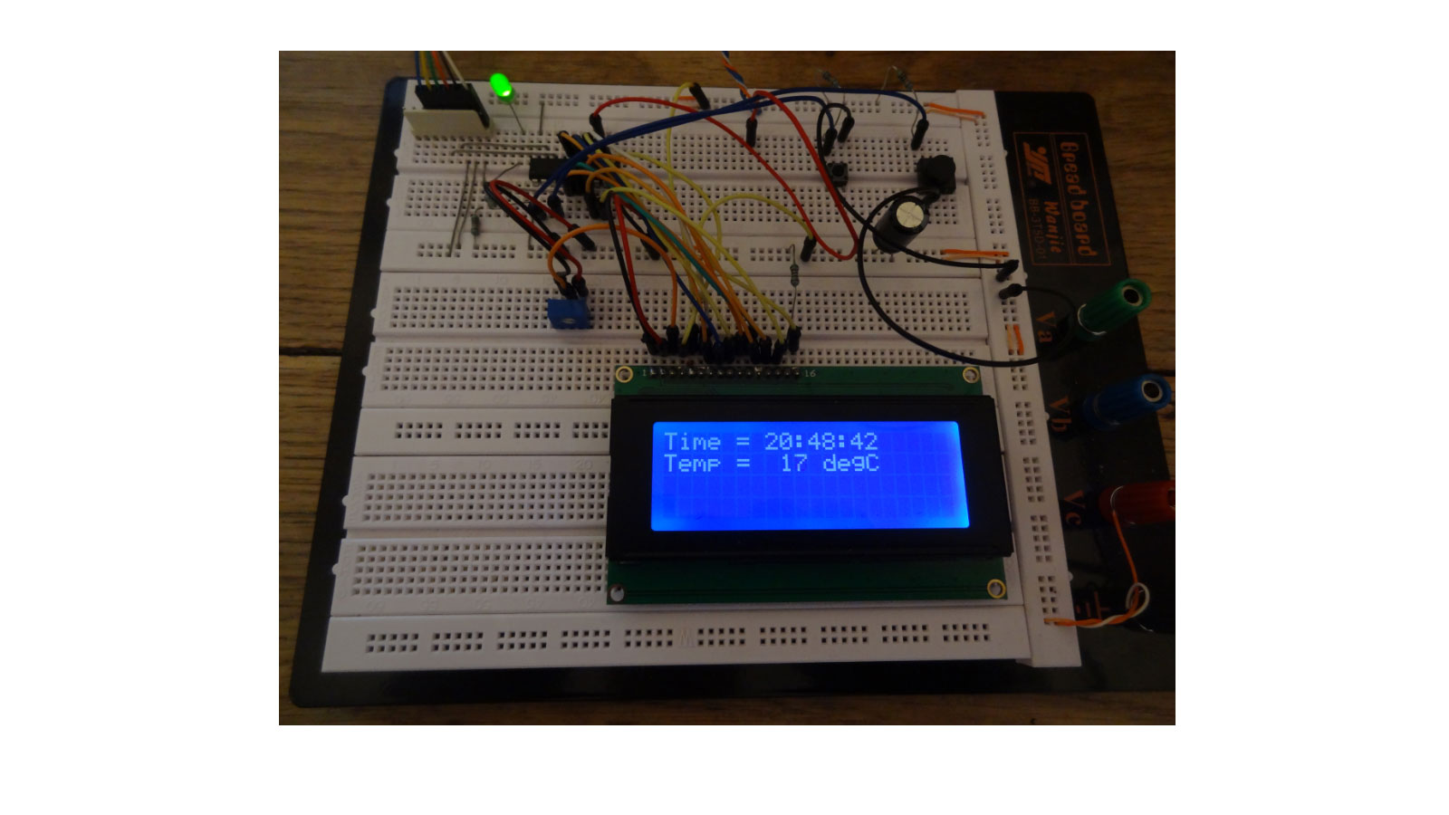
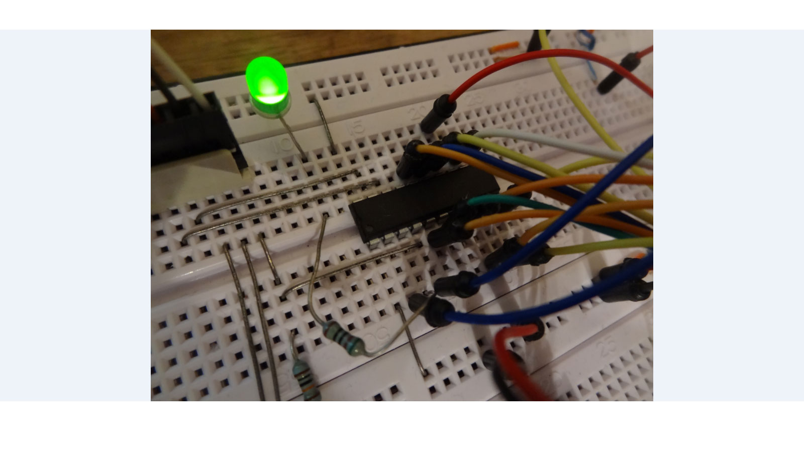
Here is the rear of the prototype which shows how simple the circuit really is - just a Microchip PIC 16f690, an LM35 temperature sensor which generates 10mV/ degree Centigrade, a contrast potentiometer for the LCD, and two push buttons to set hours and minutes of the clock.
Schematic circuit diagram of 16f690 thermometer clock project
And here is the C source code for the clock thermometer project, which has been complied with the free Microchip XC8 C complier and downloaded to the 16f690 with Microchip MPLABX IDE. Feel free to copy and use/ enhance this code to learn more about the C language and the PIC range of Microcontrollers, as I did and am still doing :-) I'd be really pleased if you would link to this page if you find it helpful.
/*
// File: lcd_thermo_clock_16f690.c
* Author: Phil Glazzard
* version 1.03 - firmware modified 1 June 2015
* Created on 26 April 2015, 14:05 - MODIFIED TRM1 PRE-LOAD TO SLOW CLOCK 11/06/2015
*/
//0XDB CHANGED TO 0XA4 IN TMR1L
// PIC16F690 Configuration Bit Settings
// 'C' source line config statements
#include <xc.h>
// #pragma config statements should precede project file includes.
// Use project enums instead of #define for ON and OFF.
// CONFIG
#pragma config FOSC = INTRCIO // Oscillator Selection bits (INTOSCIO oscillator: I/O function on RA4/OSC2/CLKOUT pin, I/O function on RA5/OSC1/CLKIN)
#pragma config WDTE = OFF // Watchdog Timer Enable bit (WDT disabled and can be enabled by SWDTEN bit of the WDTCON register)
#pragma config PWRTE = OFF // Power-up Timer Enable bit (PWRT disabled)
#pragma config MCLRE = OFF // MCLR Pin Function Select bit (MCLR pin function is MCLR)
#pragma config CP = OFF // Code Protection bit (Program memory code protection is disabled)
#pragma config CPD = OFF // Data Code Protection bit (Data memory code protection is disabled)
#pragma config BOREN = OFF // Brown-out Reset Selection bits (BOR disabled)
#pragma config IESO = OFF // Internal External Switchover bit (Internal External Switchover mode is disabled)
#pragma config FCMEN = OFF // Fail-Safe Clock Monitor Enabled bit (Fail-Safe Clock Monitor is disabled)
#define _XTAL_FREQ 4000000 // 4MHz clock defined for __delay_ms() function
#define RS PORTBbits.RB7 // RS = RB7
#define E PORTBbits.RB5 // E = RB5
int thous, huns, tens, units; // define global variables
int temp, temp1;
char tick,seconds_lsb,seconds_msb, seconds, minutes,minute_msb, minute_lsb, minutes_msb, hundreds_lsb, hundreds_msb, hours = 0;
void config_timer1(void)
{
TMR1IF = 0; //clear timer1 interrupt flag
TMR1L = 0; // clear low byte of 16 bit timer1
TMR1H = 0; // clear high byte of 16 bit timer1
T1CONbits.T1CKPS0 = 1; // select 1:8 pre-scaler
T1CONbits.T1CKPS1 = 1;
PIE1bits.TMR1IE = 1; //enable timer1 interrupt
INTCONbits.PEIE = 1; //enable peripheral interrupt enable
INTCONbits.GIE = 1; // enable global interrupt enable
}
void timer1_on(void)
{
TMR1H = 0x0B; // pre-load 16 bit timer1 with 0x0BA4
TMR1L = 0xA4; // 0.5 sec/ 2Hz frequency before overflow
T1CONbits.TMR1ON = 1; // start timer1
}
int interrupt isr (int)
{
if (TMR1IF == 1) // check to see if the interrupt was caused by TMR1 overflowing
{
TMR1ON = 0; // turn TMR1 off
seconds = seconds + 1; // increment seconds variable
TMR1H = 0x0B; // pre-load 16 bit timer1 with 0x0BA4
TMR1L = 0xA4; // 0.5 sec/ 2Hz frequency before overflow
T1CONbits.TMR1ON = 1; // start timer
TMR1IF = 0; // clear TMR1 interrupt flag
RA4 = seconds; // flip RA4 each second to flash LED at 1 Hz
temp1 = ADRESL; //store low byte of ADC conversion in temp1
temp1 = temp1 + (ADRESH <<8);//shift high byte of ADC conversion 8 bits left
//and add to temp1 to give 10 bit ADC result.
temp = (int)(temp1 /0.2046);//cast expression as an integer to avoid floating
//point arithmetic.
// 102.3 = 5V (Vref)so 10mV = 1deg C = 102.3/500 = 0.2046
ADIF = 0; // clear the ADC interrupt flag ready for next conversion
}
}
void clock()
{
E = 1; // creates a 1ms pulse to clock commands and data
__delay_ms(1); // into the LCD module
E = 0;
}
void lcd_initialisation()
{
__delay_ms(100); // 100ms delay after 'power on'
RS = 0;
PORTC = 0x30; //Function set RS RW D7 D6 D5 D4 D3 D2 D1 D0
__delay_ms(5); // 0 0 0 0 1 1 0 0 0 0 = 0x30
clock();
RS = 0;
PORTC = 0x30; //Function set RS RW D7 D6 D5 D4 D3 D2 D1 D0
__delay_us(100); // 0 0 0 0 1 1 0 0 0 0 = 0x30
clock();
RS = 0;
PORTC = 0x30; //Function set RS RW D7 D6 D5 D4 D3 D2 D1 D0
__delay_us(100); // 0 0 0 0 1 1 0 0 0 0 = 0x30
clock();
RS = 0;
PORTC = 0x38; //Function set RS RW D7 D6 D5 D4 D3 D2 D1 D0
clock(); // 0 0 0 0 1 1 1 0 0 0 = 0x38
__delay_us(200);
RS = 0;
PORTC = 0x08; //Display off
clock();
__delay_ms(1);
RS = 0;
PORTC = 0x01; // clear display
clock();
__delay_ms(10);
RS = 0;
PORTC = 0x06; // entry mode set
clock();
__delay_ms(1);
RS = 0;
PORTC = 0x0C; // LCD display ON, cursor off, cursor blinking off
clock();
__delay_ms(1);
}
void clear_lcd()
{
RS=0;
PORTC = 0x0F;
clock();
__delay_ms(1);
}
void config_ports(void)
{
//********************************************
//*PORTC 7 6 5 4 3 2 1 0 *
//* LCD DATA D7 D6 D5 D4 D3 D2 D1 D0 *
//*PORTB 7 5 *
//*CONTROL RS E *
//********************************************
TRISC = 0x00; //all PORTC pins are outputs
TRISBbits.TRISB4 = 1; //RB4 is an input pin
TRISBbits.TRISB5 = 0; //RB5 pin is an output E
TRISBbits.TRISB7 = 0; //RB7 pin is an output RS
TRISAbits.TRISA5 = 1; //RA5 is an input (hours set)
TRISAbits.TRISA3 = 1; //RA3 is an input (minutes set)
TRISAbits.TRISA4 = 0; //RA4 is an output (LED flash each second)
}
void config_adc(void)
{
ANSELHbits.ANS10 = 1; // AD channel AN10 is enabled (RB4 pin)
ADCON1bits.ADCS0 = 1; // Fosc/16 selected conv clock speed
ADCON1bits.ADCS1 = 0; //ADCS bits = 101 for Fosc/16
ADCON1bits.ADCS2 = 1;
ADCON0bits.VCFG = 0; //use external Vref on pin 18
//LM35 = 10mV/degC so 1V = 100 deg C
//Vref = 1.023V
ADCON0bits.CHS0 = 0; //select ADC channel AN10 so CHSbits = 1010
ADCON0bits.CHS1 = 1;
ADCON0bits.CHS2 = 0;
ADCON0bits.CHS3 = 1;
ADCON0bits.ADFM = 1; //Right justified 10 bit ADC result in
// ADREH and ADRESL
ADCON0bits.ADON = 1; // AD module switched ON
}
void set_adc_interrupt()
{
PIR1bits.ADIF = 0; //clear ADC interrupt flag
PIE1bits.ADIE = 1; // enable AD interrupt
INTCONbits.PEIE = 1; //enable all unmasked peripheral interrupts
INTCONbits.GIE = 1; //enable all unmasked global interrupts
}
void adc_conversion()
{
ADCON0bits.GO_DONE = 1; // start AD conversion
}
void display_temp()
{
RS = 0; // put LCD in command mode
PORTC = 0xC7; //start displaying temp at position 8 line 2
clock();
}
void display_time()
{
RS = 0; // put LCD in command mode
PORTC = 0x80; //start displaying time at position 1 line 1
clock();
RS = 1; // put LCD in data mode
char i = 6; // i takes values 0,1,2,3,4,5,6
char arr[7]= {0x54,0x69,0x6D,0x65,0x20,0x3D, 0x20};// Time_=_ ( _ is a white space)
for (i = 0; i < 7; i++)
{
PORTC = arr[i];
clock();
}
}
void write_temp()
{
RS = 1; // LCD in data mode
thous = temp/1000; // extract thousands digit
if (thous > 0) //
{
PORTC = thous + 0x30; // only display thous if thous > 0
// add h'30 offset to get ascii character
clock();
}
else
{
RS = 1;
PORTC = 0x20; // Suppress '0' in temp ie 018 becomes _18 (_ is white space)
clock();
}
RS = 1;
huns = (temp%1000)/100; // extract hundreds digit
PORTC = huns + 0x30; // add h'30 offset to get ascii character
clock();
RS = 1;
tens = (temp%100)/10; //extract tens digit
PORTC = tens + 0x30; // add h'30 offset to get ascii character
clock();
RS = 1;
PORTC = 0xDF; // write superscript O
clock();
RS = 1;
PORTC = 0x43; // write degC - C
clock();
RS = 0;
PORTC = 0x0C; // cursor off, blinking off
clock();
}
void write_time()
{
RS = 1;
tick = seconds/2; // seconds = 2Hz so tick = 1Hz
seconds_lsb = tick%10; // extract seconds_lsb
seconds_msb = tick/10; // extract seconds_msb
minute_lsb = minutes%10; // extract minute_lsb
minute_msb = minutes/10; // extract minute_msb
minutes_msb = minute_msb%10;// extract minutes_msb
hundreds_lsb = hours%10; // extract hundreds_lsb
hundreds_msb = hours/10; // extract hundreds_msb
{
PORTC = hundreds_msb + 0x30; // write hundreds_msb with offset of 0x30 to get ascii char
clock();
}
{
PORTC = hundreds_lsb + 0x30; // write hundreds_lsb with offset of 0x30 to get ascii char
clock();
}
{
PORTC = 0x3A; // write colon (:) to seperate hours from minutes
clock();
}
if (minute_msb == 6) // overcomes problem of briefly displaying
{ // 60:00 when going from 59:59 to 00:00
PORTC = 0x00 + 0x30; //00:00 + ASCII offset of 0x30
clock();
}
else
{ PORTC = minute_msb + 0x30; // write minute_msb with offset of 0x30 to get ascii char
clock();
}
{
PORTC = minute_lsb + 0x30; // write minute_lsb with offset of 0x30 to get ascii char
clock();
}
{
PORTC = 0x3A; // write colon (:) to seperate minutes from seconds
clock();
}
{ PORTC = seconds_msb + 0x30; // write seconds_msb with offset of 0x30 to get ascii char
clock();
}
{ PORTC = seconds_lsb + 0x30; // write seconds_lsb with offset of 0x30 to get ascii char
clock();
}
}
void text()
{
RS = 0; // put LCD in write command mode
PORTC = 0xC0; //start writing text at position 1 line 2
clock();
char c; // define loop counter variable
RS = 1; //put LCD in write data mode
int arr [7]= {0x54,0x65,0x6D,0x70,0x20,0x3D,0x20};// Temp_=_
for (c = 0; c < 7; c++) // write 7 characters to LCD
{
PORTC = arr [c]; //write Temp_=_ on LCD
clock();
}
}
void main(void)
{
config_ports();
config_adc();
set_adc_interrupt();
config_timer1();
lcd_initialisation();
clear_lcd();
__delay_ms(10);
timer1_on();
text(); //write Temp_=_ to lcd
while (1) // repeat this loop forever
{
display_time(); // start writing 'Time_=_' at position 1 line 1 (_ is white space)
write_time(); // write hours:minutes:seconds to LCD - at power on default is 00:00:00
display_temp(); // start writing 'Temp_=_' at position 1 line 2 (_ is white space)
adc_conversion(); // start AD convesion
write_temp(); //extract the three digits and display them on LCD
// and write _degC after the temperature data
// temp measurement range is 0 - 102 degC
if (RA5 == 0) // set hours button pressed pin 2
{
hours = hours + 1; // increment hours
__delay_ms(200);
}
if (RA3 == 0) // minutes button pressed pin 4
{
minutes = minutes + 1;// increment minutes on each button press
seconds = 0;
__delay_ms(200);
}
if ( seconds == 120) // 120 (2Hz) seconds = 1 minute
{
seconds = 0;
minutes = minutes + 1;// increment minutes when seconds = 0
}
if (minute_msb == 6) // detect if miniutes = 60 and clear minutes
{
minute_msb = 0;
minutes = 0;
hours = hours + 1; // increment hours
}
if (hours == 24)
{
hours = 0; // when hours = 24 clear hours/ minutes/ seconds
minutes = 0;
seconds = 0;
}
}
}